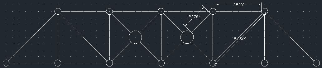
The design goals for the A2 design were to have structural integrity, maintain a relatively low cost, and incorporate at least minimal aesthetics into the design. For the elevation, a combination of triangle and X shaped cross sections were used to support the weight of the bridge itself and allow it to support more weight as well. A very rough CAD drawing of the elevation can be seen below. Note that the dimensions are slightly incorrect. Each horizontal or vertical member (which are all the same length/height) are in actuality 3 3/8". The longer diagonal members (which are also all the same length) are actually 5"; the smaller diagonal members are really 2 1/8". Here is the elevation view:

As shown in the photo above, the two mid-sections of the bridge utilize an X design in order to create extra strength where it will be needed the most. The sections on either side of the X sections were initially made with X designs as well but in an effort to slightly reduce cost, it was decided that the triangular sections were strong enough. The two outer-most sections were simple triangles rather than complete rectangles in order to reduce the cost as well. At the ends the bridge will be supported from below enough to made the rectangular shape unnecessary.
For the plan, a similar approach was taken to mimic the elevation design of the bridge. X-shapes were used in the two innermost sections whereas the rest were made with only two triangles. The plan view can be seen below.
After completing the Truss Bill of Materials, this design is estimated to cost $227,000. This is very similar to the cost of the bridge designed by the group in Week 3.
Through designing this bridge with K'nex pieces in class, the limitations of only being able to use 45 degree angles became incredibly apparent. Many of the designs created using WPBD in Weeks 1-3 utilized a variety of angles and thus made it difficult to transitition into using only 45 degrees.


No comments:
Post a Comment