Wednesday, May 30, 2012

Week 9


Last week was dedicated to testing and rebuilding our bridge to get the best weight to cost ratio. First we tested our original design with the truss on top, which held about 25 lbs. We tried removing the truss to reduce cost and got it to hold 20 lbs, with slightly lower cost per pound held 
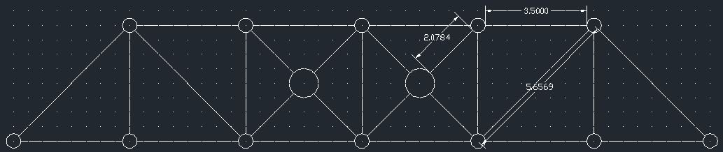
up. We tried another approach after that, placing the truss on the bottom and extending it by one section on both ends, and got a huge increase in weight held, up to 33 lbs. It was our most expensive design, but it had the best weight to cost ratio as well. Placing the truss on the bottom helped the bridge better distribute the weight placed on it and remain standing for longer. Our next steps is to isolate the areas that gave way first and reinforce them to create a better bridge. We're also placing small members on the gusset plates at both ends to increase pull out force necessary to cause the end beams to fly off. Our goal is to get the best weight to cost ratio, so we'll be experimenting with different ideas this week to see if we get better numbers, and collaborate the best aspects of each design to create our final design.


I learned a lot about the bridge design process from taking this course. I expanded on my knowledge on trusses and learned about the cost versus strength dynamic in bridge building. I also learned about a few other factors that affect  a bridge in real life, like wind and torsion forces. There was  a lot of emphasis in this course about how our designs would differ from a real bridge and what factors we weren't counting in our simulations, so I learned quite a bit about the differences between the expected design and the real live creation. One of the most important things I learned from bridge design was that weight distribution is extremely  important in construction. A design that can manage to spread weight out evenly causes less stress joints to each joints, preventing the case of one beam or gusset plate from being subjected to too much tension or compression and failing. Bridge design also helped me realize the importance in the design process when it comes to big projects and how everything must be calculated before any real work is done when it comes to large projects.

Tuesday, May 29, 2012

Week 9

In the past week, we ran a few tests on our bridge design to test our ideas.  We built most of the bridge in week 7 so that we could concentrate on working out the issues in week 8 to prepare for the formal test.  We tested the positioning of a smaller truss by placing it on the top of the bridge, on the bottom of the bridge, and without it all together.  We found that it is worth the cost to have the smaller truss attached to the bottom of the bridge.  When we tested the bridge with the smaller truss connected to the top, it held a little over 20 pounds.  We then decided to remove the small truss because the weight increase was not beneficial in relation to the cost. When we tested the bridge without the small truss it held slightly less than the first test.  The cost to weight ratio was lowered.  Then we expanded the small truss and added it to the bottom of the bridge and tested it.  The results showed that this was the best design.  The cost was increased slightly but it was able to support much more weight.  Overall it held a total of 33 pounds and had the lowest cost to weight ratio.  An issue that we faced this week was the gusset plates on the end were the weak points.  In order to fix this, we added small members to the open spaces to increase the pull out force of the gusset plates.  In the coming week, we plan to test our final design, calculate the cost to weight ratio and analyze the failure.

This course has taught me a lot about the bridge design process.  There are so many possibilities for the design of a simple bridge.  Our task was to create two bridges, one that had a 24" span and one that had a 36" span.  Each group had a design that was very unique to complete the same task.  One major design element that was reinforced was that triangles are the strongest shape because the shape cannot change without the lengths of one member being changed.  Another thing I learned using West Point Bridge Designer is that the force/strength ratio should be as close to one as possible without going over one while still decreasing the cost.  There comes a point where the cost stops decreasing because the materials are custom sizes and they cannot tolerate any more weight for their size.  When designing a bridge, there is a perfect ratio that needs to be found.  There comes a point where the bridge is not beneficial for its purpose.  The design has a huge impact on its stability, cost, and success.  There is a happy medium when designing a bridge.  If the bridge is too tall, much more supports are needed to make it successful.  If the bridge is too short, there are more supports needed to make it work.  There is a height somewhere between the two where the cost is the lowest while still being successful.

Cameron Week 9


Over the course of this term, I have learned many things about the bridge design process.  One thing that I had already known, but gained more of an understanding of is the fact that triangles are the most structurally sound shape.  I knew that this was the case, but was not sure of the reasoning behind it.  It makes sense because the triangle is the only shape that can not change unless the lengths of each side is changed. 

Another element of bridge design which I learned through this course is that there is a point where too much structure begins to counteract the intent of the design.  In simpler terms, if a bridge is incredibly tall, the benefit of the extra support from above is far less than if the bridge was shorter.  Yes, increasing the height of some bridge designs will make them more structurally sound, but there is a point where this benefit is reduced.  This point is why there were so many designs from the 1900s because bridge designers tried so many different ideas not knowing what the best proportion was/is.

Last week in class, we worked on perfecting the bridge that we had began creating in week 8.  We started class by testing what we had built during the previous week, which included a secondary truss component above the main portion of the truss.  When first tested the bridge held about 20 pounds.  For our second test, we removed the secondary upper truss and tested just the main truss.  This dramatically reduced the cost while keeping the weight relatively stable; thus lowering the ratio of cost to weight.  Having enough extra time for a third test, we decided to test the bridge using a secondary lower truss which spanned almost 8 inches more than the previously tested upper truss.  This lower truss added to the cost of the initially tested bridge, but held significantly more weight (33.6 pounds).  After computing all three ratios, we found that the bridge with the lower truss proved to hold the most weight per dollar. 

After conducting our three tests, we then began to consider the effects of filling all of the gaps in our outermost gusset plates.  We noticed that all three of our proposed designs failed at the outer gusset plates.  We added the small white members to each available space to increase the force needed for a member to pull out of the newly-filled gusset plates.

In the coming week, we hope to test our final design.  We expect it to fail in a similar fashion as our proposed designs did.  After testing we will complete a more in depth analysis as to why the bridge failed.

Wednesday, May 23, 2012

Week 8

The method of joints is fairly useful in figuring out what patterns might work better in building the overall bridge but for real life bridges, the method of joints will at best give you a  good estimate of what to do. It does not account for all of the forces applied to a bridge and other factors such as wear and tear. It's a good starting point for designing a bridge and understanding how bridges distribute weight. It also doesn't account for uneven weight distribution all that well so I think a tool like WPBD would be better for making all the calculations involved in a moving object applying stress on the bridge. We would also have to consider other factors such as wind and durability, as well as torsion forces that can occur when testing out a bridge.

Last week in class, we worked on creating our 36" bridge and exploring new ways of placing the k'nex pieces so that they interlock with each other better. We also worked with the method of joints to see how stress affects truss designs and our bridge to understand it a bit better. This week we plan on further working on our bridge and testing it out if we get the opportunity.

A3- THOMAS

Above are the calculations for forces acting on the bridge and the simulation on BridgeDesigner. Since all the angles we used were 45 degree or 90 degree angles, there was a pattern in the tension and compression on each member. The method of joints is useful for figuring out how the force applied onto a bridge will be distributed throughout the bridge and help us come up with an optimal design.
This is an analysis of our K'nex bridge and the method of joints can also be applied here to figure out how our bridge distributes the stress placed upon it and engineer it better in order to better distribute the weight and be a stronger bridge.

Tuesday, May 22, 2012

Week 8

In the past week, we began working on designing and building our 36" span bridge.  We used the same basic design from the 24" span bridge but we expanded it so the span reached the 36" minimum.  We chose to work on our bridge in class instead of the truss analysis because we agreed that this was using our time more efficiently.  It would be easier to work on the truss analysis on our own at home and work together on the bridge in class.  The truss analysis was relatively simple to do on our own.  This week we are planning on focusing on slightly changing our bridge design in order to increase the load it is capable of supporting.  We will perform practice tests in class to prepare for the formal testing in week 9.  By performing practice tests and using the method of joints, we can see where the weak spots are and concentrate on making them stronger.  Our major accomplishment was getting a good start on our 36" span bridge and completing the method of joints in order to improve and analyze our design.  An issue that we encountered this week was using the bridge designer program, it does not allow any combination of nodes and members.  Our original design did not satisfy the specifications needed to successfully perform the calculation.  We had to slightly simplify our design in order to get results.

After becoming familiar with the Method of Joints for truss analysis, I do not thing this type of analysis is sufficient for a real bridge.  This method of analysis only takes into account the horizontal and vertical forces.  There are many other forces acting on bridges in the real world.  This method also only applies the load on the bridge to one spot on the bridge, this does not compare to loads on real bridges.  The loads are constantly changing position because traffic is constantly changing position and the load changes.  The bridge designer and the method of joints also does not account for the weight of the bridge itself.  This would be an important factor in the real world.  I would like to analyze the forces acting on the bridge in other directions other than horizontal and vertical.  In the real world, there is forces from wind and torsional forces that also exert forces on the bridge.  The method similar to the method of joints could be used but in a third dimension.  The force from the wind is going to be hard to predict because it is always different but we could use a rough overestimation to ensure the bridge will be able to withstand the maximum force applied to it.

A3-HOWARD


Calculations for Method of Joints:

The negative values indicate compression, the positive values indicate tension.  

Diagram of force on each member:


Bridge Designer Analysis Diagram:


In order for the results of the hand analysis to correspond to the online Bridge Designer analysis, the ratios of the length of the members must be correct to ensure that the angles are correct.  Each member must be scaled to the size of the actual length.  The angles between the members in the actual bridge must match the angles in the online bridge designer.  Members in the actual bridge that are equal lengths must also be equal lengths in the online bridge designer.  If the ratio between the members stays the same, the angles will also stay the same.


Knex Bridge Analysis Diagram:

This type of analysis is helpful in analyzing the Knex bridges.  The force on each connection can be estimated and how much force is necessary before a connection is broken because we can determine how much force each connector and member can support.  Using the method of joints and the bridge designer, we can estimate how much load the bridge can hold before the connections are broken from too much tension or compression force.  This information can be used to improve the design of the Knex bridge in order to hold a greater load with less members.  An issue I encountered with Bridge Designer is that it does not allow any design, the number of nodes is related to the number of members.  We had to reconfigure slightly our design to allow the bridge designer to calculate the tension and compression.

Cameron Week 8


After working with the Method of Joints Truss Analysis, I do not believe that this type of analysis would be sufficient for a bridge in the real world.  In the real world the force is not constantly applied to the same position of the bridge, in most cases the force being applied is moving across the bridge in the form of a car, a train, a tractor trailer, or perhaps a person walking across a foot bridge.  This method assumes a constant force in the same position which is ideal, but not realistic. 

One concept that this method does not take into consideration are the forces acting on the side of the bridge.  In the real world there may be wind and/or torsional forces that could exert forces on the faces of the truss.  To incorporate these forces it could be useful to use the same method and add a third dimension.  The only reservation to this suggestion is that wind may be somewhat unpredictable, but a rough overestimation could be used to determine whether the bridge would be able to withstand the forces acting on it.

Last week in class we chose to work on our bridge rather than compute the truss analysis.  We felt that this was the best use of our time as the truss analysis proved to be relatively simple.  We used elements of our 24" bridge and elongated them to be able to span 36".  This week our class time will be devoted to testing and tweaking the bridge we created last week in class before the actual testing in Week 9.

A3-Cameron


Above are the pages of work done in analyzing the truss as defined in the A3 instructions.  The forces calculated can be viewed in the table on the top of the first page.  A negative sign denotes compression, while a positive number denotes tension.  Below is a screenshot of the Bridge Designer replication of this analysis.
To allow the hand analysis to correspond to that of the Bridge Designer, it is necessary to count the number of spaces between each node on Bridge Designer.  It was given in the directions that the distance between each horizontal node was equidistant meaning that each interval should be the same between a set of two horizontal nodes. 

For the bridge that was created to span 24 inches, the Bridge Designer analysis can be viewed below. These calculations were created using a 20 pound load in the center of the bridge.

This type of analysis could also be used in analyzing the K'Nex bridges.  With an understanding of how each type of connection will ultimately affect the pull out force of the K'Nex, one would be able to analyze the bridge created with K'Nex.  The average pull out force of each type of connection can be used to predict what the rough pull out force would be for each connection of the bridge.  Proceeding further, one could then utilize the method of joints in order to determine the force on each member and predict whether the joint would be able to withstand that magnitude of force being exerted on it. 

Wednesday, May 16, 2012

Week 7


Last week in class we had the chance to test out our bridge. With the new gusset plates, the bridge was able to hold 21.4 pounds while retaining its $216,000 cost. It cost us $10,189 per pound and it spanned about 2 feet in length. Using a different set of gusset plates gave us joints that didn't come apart too easily and allowed us to use better angles for connections. We simply tried to have a low cost to weight ratio and use simple shapes to build our bridge. We placed focus on distributing any weight placed on the bridge and reinforce the joints. Our bridge performed pretty well and we were happy with the results.

Using K'nex made things a bit harder to understand than using WPBD. We can't see any of the stress or tension on individual parts nor can we use as many angles. I still hold on to the belief that spreading out the weight as equally as we can to all the different parts would give us the best cost to weight ratio so my goal is to find the shape that accomplishes that. The shape that I had the best success with in WPBD was an arc with triangles supporting it but this cannot be done with the K'nex since we were limited in angles and part lengths. The joints on the K'nex are also weaker than WPBD as they are more prone to coming apart under stress. Figuring out how the force is applied to each part through equations would possibly help us spread out the weight among each part and help us develop a better cost to weight ratio. This week we plan to modify our design to fit the 36" criteria for the next group bridge. We plan on mainly using the elements of our current bridge but we might make changes depending on whether they lower the cost to weight ratio or not.

Tuesday, May 15, 2012

Week 7


In the past week, we tested our bridge that was constructed in week 5.  The test consisted of suspending a bucket from the bridge and loading sand into the bucket until the bridge failed.  Our bridge had a total of 142 members for a total cost of $216,000.  It was able to hold 21.2 pounds before breaking.  The cost per load ratio was $10,189 per pound.  In the previous week, our bridge design failed under the weight of one battery so we were pleasantly surprised when our new design was able to hold 21.2 pounds.  This week we will begin working on our next bridge design that will span 36".  We are planning on using aspects from our previous design as a starting point for this larger bridge.  We are planning on adding more support members to increase the amount of weight that the bridge can hold.  Our main goal is to have the lowest cost per load ratio.  Our biggest accomplishment this week was testing our 24" bridge and analyzing the results to improve the next design.  We did not encounter any major issues this week.  

It was very helpful to be given the information for compression and tension force/strength ratios in West Point Bridge Designer.  These values would be helpful if they were associated with the Knex that were used.  It would also be useful to know the force on the gusset plates and how much force they could withstand. The gusset plates ere the main source of failure int eh Knex test.  If we knew the load on them, the design could be slightly changed to accomplish the greatest amount of force that can be put on the gusset plates.  It would be very challenging to figure out the force/strength ratios because the tension and compression are not extremely apparent like they were in West Point Bridge Designer.  It would also be hard to measure these forces on Knex.  The force on the gusset plates can be taken into account to find the total force acting on each plate.  It would be more complicated than one simple equation because you have to take into account how each plate puts pressure on the surrounding plates and members.   

Week 7 Update


In terms of the Knex project, it would be beneficial to know similar information to that given in WPBD.  The compression force/strength ratio as well as the tension force/strength ratio would be important pieces of information to have before testing the bridge.  Another helpful piece of information would be the overall force on the gusset plates.  This would allow us to tweak the design to ensure that the forces on the gusset plates were evenly distributed and not all concentrated on one junction.

Determining the force on the gusset plates could be fairly simple.  Using free-body diagrams to interpret all of the forces acting on the plate would allow us to measure the overall force acting on it.  This can then be plugged into Newton's second law which tells us that the sum of the forces acting on an object is equal to the mass of the object multiplied by the acceleration of the object; this will give us the "acceleration" of each gusset plate.  In an ideal setting, the acceleration should be zero and to achieve this we would need to balance out all forces acting on the gusset plates so that there would be no acceleration.   The only conceivable issue with using free-body diagrams to compute the force acting on each gusset plate would be finding the tension forces of the upper members.  We know the force of gravity, but it may be more difficult to determine the force acting on the gusset plate from above.

To determine the force/strength ratios would be very challenging.  For the purposes of the Knex bridges, there is no setting where we can exaggerate the deflection of the bridge in order to determine which members are compression and which are tensing. 

Last week in lab, the bridge created in week 5 was tested using a bucket of sand.  Our bridge was able to hold a maximum of 21.4 pounds at a cost of $216,000, giving it a weight/cost ratio of 9.91*10^-5 pounds/dollar.  We were slightly surprised by these results as we did not know what to expect.  We had tested the structure during week 5 and it had failed under the weight of one battery. 

This week we hope to begin working on a bridge which will span 36".  Our previous design was preserved and will be used as a starting block for the larger bridge.  More support members will be added and possibly there will be the addition of a secondary upper truss.

Wednesday, May 9, 2012

Week 6


Last week, we experimented with the K'nex bridge and tried to come up with something that incorporates key elements from all our designs. Our creation was a bit different from our designs because of the limitations of the K'nex pieces. I originally drew the designs with the design capabilities of WPBD in mind, but the K'nex pieces fall short of being able to do what WPBD can do. The K'nex pieces can only be connected in very limited angles, the pieces themselves are limited, and small flaws like overused gusset plates becoming loose can present to be a major problem like we experienced last week. Our design was initially strong but the gusset plates were loose enough to slip out when a weight was placed on it. We had to find and use the full circle gusset plates with less wear on them to create stronger bonds.

Our design philosophy revolves around minimizing cost while maximizing the ability to hold weight, aiming for the best ratio of the two. My approach to this has been to spread the weight out as evenly as I can among all the pieces so too much stress won't be placed on a single joint that can cause the whole bridge to fail. Creating a bridge that can spread out the weight placed on it will allow us to use each piece to its maximum extent and save money on building reinforcements on key parts. This design philosophy held through very well in our WPBD tests so it should do well in K'nex, even with the differences between the two mediums.

Tuesday, May 8, 2012

Week 6


In the past week we built a bridge out of Knex that was two feet long.  We had three designs that were similar in many ways.  They all had the same general shape and use of triangles, the only variations were the length of members and slight placement.  We used the best components of each bridge to build our group bridge.  We used small members to make the overall bridge stronger.  We also did an informal test on our bridge which resulted in quick failure.  We found that the connectors we used in certain spots were too loose and not placed effectively.  This was the only major problem we came across this week.  We changed the positioning of the connectors and used some that snap together tighter.  Our goal for this week is to test our Knex bridge and analyze how the bridge failed.  A cost to weight ratio will also be calculated to compare to our peers results.

After working with the different Knex pieces in class, my views of the similarities and differences between Knex and West Point Bridge Designer have not changed.  In my opinion, it would be very different working with Knex rather than designing a "real" bridge made of steel spanning 20 feet.  The Knex still limit the design possibilities.  The Knex only connect at angles in increments of 45 degrees.  A steel bridge would have much more freedom in the aesthetics because any angle can be used and custom pieces can be made.  The design process for a "real" steel bridge is much more complicated than using Knex.  We can experiment with the Knex and different designs by quickly making a model and changing it by simply snapping pieces into connectors.  A steel bridge is not this simple and more factors have to be taken into account.  

Sunday, May 6, 2012

Week 6

After working with the K'nex pieces in class during week 5, my original opinion of the difference between K'nex and WPBD has not changed.  I still feel that there are far fewer variations that can be made using the K'nex pieces.  In relation to designing a bridge out of steel to span 20 feet, the K'nex pieces will still have far fewer possibilities because the steel can be welded and/or bolted to the gusset plates in order to form any desired angle.  The K'nex are only able to meet at 45 degree angles.  Overall, the process for both types of design will be similar, but more thought needs to be put into the 20 foot steel bridge before production because it is not a matter of snapping pieces in and out of connectors to change the design.

Last week, our time was devoted to designing and informally testing a bridge made out of K'nex.  We reviewed the three designs which were created in the previous week and compiled the best elements of each design to be incorporated into our group design.  We found that all three designs were very similar with slight variations in member length.  We chose to go with the smaller members in order to maintain more structural integrity. 

This week our goal is to test our bridge and analyze the results of how the bridge failed and under how much weight.  This will allow us to determine a cost to weight ratio which we will be able to compare to other groups in the class.

Wednesday, May 2, 2012

Week 5

Last week, we got familiar with the K'nex pieces after experimenting and playing around with them during class. We learned a good bit about finding and using resources through the guest speaker also. After examining the K'nex pieces our group felt there weren't many directions we could take with these constraints and our designs tended to be very similar. Our goal is to make a bridge with simple shapes that is both inexpensive and capable of holding up large loads. To prepare for our A1 assignment this week, I've been sketching designs on paper whenever I could and picked my favorite one to sketch out in better detail and scan into the computer for the post. I also came up with my best goal for bridge building, redistributing the tension on the pieces. If the bridge was able to redistribute any tension placed on it evenly throughout the pieces, each piece would be able to take more weight and the bridge will be significantly stronger without worry of one piece being under extreme stress. I also see the shapes used in bridge design to serve this purpose of redistributing tension as I observe real world examples. I'm not too sure how the gusset plates will be able to handle stress in K'nex yet so there is still a lot of testing to be done in order to come up with a good final design.

We will be building prototypes in class soon so I hope to test out my design and see its ability to hold and manage weight and try different methods to get a better grasp of good bridge design.

A2 - THOMAS


My bridge is designed to accomplish two goals. The first goal is to spread the weight out as evenly throughout the bridge as I could in order to let the bridge support more weight. The second goal was to keep the cost as low as possible, and that was done using a few larger pieces to build the bridge instead of numerous smaller pieces. Larger pieces means less expensive connectors. This bridge is built with the limitations in angles and parts of the K'nex pieces but since custom parts were unavailable, I had to improvise for some connections. I drew the bridge and centered it around triangles since its a really good shape to support weight and redistribute the tensions caused by the weight. I tried to create an-arch that was still capable of holding up the device on top but I had to change the design to make it a bit of a triangle based arch in order for it to fit the constraints. My aim was to achieve something like the arc with triangles design I had from WPBD but the K'nex's restrictions on angles and parts makes it non-viable. I learned more about working under constraints and how much of an obstacle it can present at times. I felt further improvements could only be made after testing my current bridge design and comparing the capabilities of my original bridge and any iterations of it in order to come up with the best bridge design.

Figure 1: Sketch and plans for bridge

Figure 2: Cost Calculations

Tuesday, May 1, 2012

Week 5


In the past week, we began experimenting with converting our bridge designs into Knex models.  We familiarized ourselves with the available Knex pieces and joints.  There are limited sizes of Knex pieces and they can only be joined in increments of 45 degrees.  As a result of the limited sizes and joints the designs had to be altered in order to use the right sizes and angles.  I drew my altered design in AutoCAD using the sizes and angles that will be used when building the physical model out of Knex.  In the coming week, our goal is to build our individual bridge designs out of Knex and prepare to test them.  The major accomplishments that we had this week consisted of altering our designs to be compatible with Knex and drawing our designs using computerized methods or hand drawings to get experience.  An issue that occurred this week was designing a bridge using only 45 degree angles.  Our team kept coming up with very similar, almost identical designs during lab.  We found that the designs are very limited when only 45 degree angles can be used.  It was also an issue that the members are predetermined lengths.  In some designs that I came up with, there was not a member available to fit the length I needed causing me to redesign.  

Designing bridges in West Point Bridge Designer is very different from designing bridge models out of Knex.  When using WPBD, there is a lot of variety in the angles, sizes, and thicknesses that are available.  When using Knex, the sizes are very limited and the only angles that can be used are in increments of 45 degrees.  Knex do not allow you to use custom sizes or thicknesses, they are all predetermined.  The design shapes are similar in that triangles are the most common used shape.  


A2-HOWARD


I designed my bridge as a straight truss bridge with one level.  The most common shape I used is the triangle because it is considered the strongest shape and can hold a large amount of weight.  My goal was to use the minimum number of members in order to make it cost efficient.  I found that a more simple design is usually more effective in West Point Bridge Designer so I used that knowledge in designing my Knex bridge.  I decided to use one level because adding a second level caused a large increase in cost and was not necessary.  I also made the bridge out of smaller pieces instead of a few large ones because it is stronger and the cost is not much different. 

My original design for a bridge was made in WPBD.  It was a similar shape however the angles were slightly different making the length of the members different.  I had to take into account that Knex can only be joined in increments of 45 degrees.  My design also changed in that originally I had many more joints to add support but this made the price much higher.  I decided to use a simple design that was low in price.  My design still includes all triangles however there are less of them. 

From designing this bridge, I learned that the cost is very important.  It is very hard to design a safe bridge and keep the cost relatively low.  I also learned that you have to work with what is provided.  It was challenging to come up with a unique design while limited to 45 degree connections and predetermined sizes of members.   

                     Figure 1: Elevation

                     Figure 2: Plan

   Figure 3: Bill of Materials and Cost

Week 5

During last week's lab, group members had the opportunity to work with the K'nex pieces in order to gain a feel for the various design possibilities.  They were also asked to begin creating drawings of their proposed designs using AutoCAD, Google Draw, or by hand.  It was surprising to learn the limitations of the K'nex only having 45 degree angles, but group members were able to work around this constraint to create viable designs. 

When designing bridges using the West Point Bridge Design (WPBD) software, users have a lot of flexibility in terms of angles and connections.  With the K'nex pieces there are far fewer of these options.  Angles aside, the basic designs that can be created using each method are very similar most of the time.  The basic shape is the same with triangular trusses and the occasional X design.  The WPBD allows users to create a slightly more visually appealing design.  Mainly all of the differences can be somehow drawn back to the lack of options in terms of angles with K'nex pieces. 

In the coming week, progress with the proposed designed will be made by creating actual models from the K'nex pieces.  Hopefully the group members did not all create identical designs and there will be some sort of variety when it comes time to build a prototype in class.

A2-Cameron

The design goals for the A2 design were to have structural integrity, maintain a relatively low cost, and incorporate at least minimal aesthetics into the design.  For the elevation, a combination of triangle and X shaped cross sections were used to support the weight of the bridge itself and allow it to support more weight as well.  A very rough CAD drawing of the elevation can be seen below.  Note that the dimensions are slightly incorrect.  Each horizontal or vertical member (which are all the same length/height) are in actuality 3 3/8".   The longer diagonal members (which are also all the same length) are actually 5"; the smaller diagonal members are really 2 1/8".  Here is the elevation view:

As shown in the photo above, the two mid-sections of the bridge utilize an X design in order to create extra strength where it will be needed the most.  The sections on either side of the X sections were initially made with X designs as well but in an effort to slightly reduce cost, it was decided that the triangular sections were strong enough.  The two outer-most sections were simple triangles rather than complete rectangles in order to reduce the cost as well.  At the ends the bridge will be supported from below enough to made the rectangular shape unnecessary. 

For the plan, a similar approach was taken to mimic the elevation design of the bridge.  X-shapes were used in the two innermost sections whereas the rest were made with only two triangles.  The plan view can be seen below.
After completing the Truss Bill of Materials, this design is estimated to cost $227,000.  This is very similar to the cost of the bridge designed by the group in Week 3. 

Through designing this bridge with K'nex pieces in class, the limitations of only being able to use 45 degree angles became incredibly apparent.  Many of the designs created using WPBD in Weeks 1-3 utilized a variety of angles and thus made it difficult to transitition into using only 45 degrees.